
(Note: The Easy Digi board layout has since changed. Please see an update to this article I have done for the Hudson Valley Digital Network notebook. Shout out to Wayne KB4DSF for reminding me to mention the change.)
While VOX provides a “quick win” to experience connection-less digital modes, connected-modes are timing sensitive and require the use of PTT to avoid the “transmit on” latency VOX introduces. For a long time I was stubborn and intent on making VOX work for connected-modes just on the premise of keeping to the simplest and cheapest interface possible. But I had to concede and begin anew finding a simple and cheap interface that includes PTT support for the Baofeng UV-5R.
Since my last blog entry, I have successful built an interface for the Baofeng that supports Packet Radio connected modes as well as run a traditional Packet Radio BBS. Sadly there is little if any Packet Radio activity near me if you exclude APRS. So my stations talk to themselves alot.
In this entry I will show you the interface I built for the Baofeng that supports PTT as well as the change you need to make in the Dire Wolf software TNC to use PTT. Pursuing simple and cheap simultaneously can be difficult so I decided to start with simple in order to get me the “quick win and taste of success” and then work towards cheap.
Simple Interface
I’ve mentioned in previous posts that a favorite kit I like to use as a foundation in any radio interfacing is the Easy Digi kit for $8 USD. For time and money you cannot do better in building a circuit that provides optimal isolation for audio and control signals.
In fact most of the cost in building a PC to radio interface is in the connectivity from the interface to the various radio brands. While RS-232 has been the standard control from PC to interface, the deprecation of DB9 interface from PC’s has added the cost of USB-to-Serial cables.
With that said, our parts list includes the following;
- Easy Digi Kit ($8 USD)
- Baofeng speaker/mic cable ($6 USD)
- One 3.5mm stereo male-to-male cable ($3 USD)
- 2 Male-to-Male Jumper wires ($5 USD for a bunch)
- DB9 female terminal breakout ($3 USD)
- USB audio adapter ($8 USD)
- USB-to-Serial cable ($8 USD)
My quest for the”quick win and taste of success” never includes what will I do for a case to put everything in. It is not until I have something working (consistently) and need put it in something less precarious than sprawled across my bench that I figure out enclosure options. After working with candy containers and cigarillo tins I found the cheapest case to build has been plastic electric outlet boxes and covers from home improvement stores.

The materials are not perfect but for $2 USD and a glue gun for filling gaps it keeps things contained.
Board and Cables
Once I had all the materials the build went as follows
- Solder the Easy Digi kit components to the board per the instructions provided by the kit.
- Cut the 3.5mm stereo male-to-male cable in half. Use one half for USB audio from the board and the other half for USB audio to the board.
- From the top of the board looking at the AUDIO FROM PC stencil with one of the 3.5mm cable halves, solder the audio shield to the hole on the right side of the stencil and the tip to the hole on the left side of the stencil. We will not be using the ring connection since we only need one channel of stereo audio to the radio
- From the top of the board looking at the AUDIO TO PC stencil with the other 3.5mm cable half, solder the audio shield to the hole on the left side of the stencil and the tip to the hole on right left side of the stencil. We will not be using the ring connection since audio from the radio is mono.
- While verifying which wire from the Baofeng Speaker/Mic cable goes to what tip or ring on the connector, solder the Baofeng speaker/mic cable to the board as follows:
- SPK+ to RX AUDIO point closest to R3
- SPK- to RX AUDIO point closest to R1
- MIC+ to MIC IN
- MIC- to MIC GND
PTT Jumpers
- Triggering PTT on the Baofeng requires AUDIO, PTT, and MIC grounds to be connected together. We accomplish this by adding two jumpers to the component side of the board.
- For the first jumper, solder one end of a jumper wire into PTT GND. Snip the pin from the other end of that jumper wire and solder the wire to the side of C2 closest to PTT GND.
- For the second jumper, solder one end of a jumper wire into PTT HI and the other end to the open pin on the left bottom of T2 and above the left side of R2. That happens to be the same trace as MIC GND.
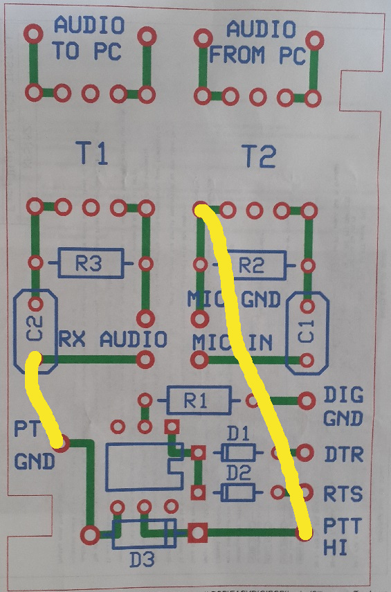
Serial and Connections
- Take three jumper wires cutting off the pins on one end of each, and strip a little insulation off the end.
- Solder the pin end of each jumper wire to DIG GND, DTR, and RTS holes on the board.
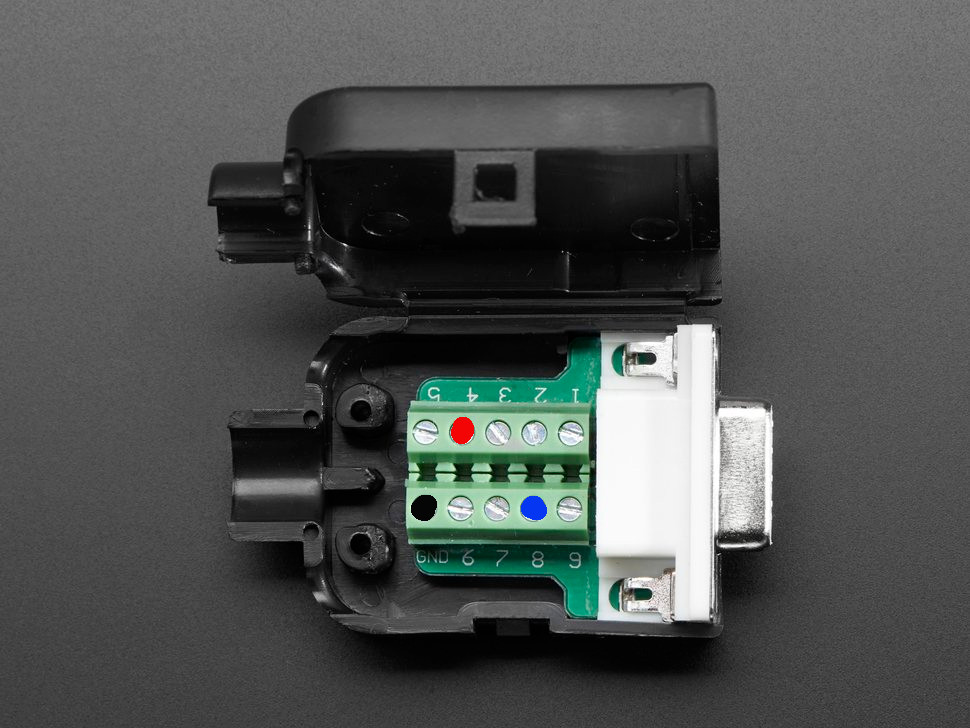
- Connect the other ends of the jumper wires to the screw terminals on the DB9 female breakout for GND (black), DTR (red), and RTS (blue) respectively as depicted in the picture below.
- Connect the USB-to-Serial cable to the PC and DB9 female connector.
- Connect the USB audio dongle to the PC and the 3.5mm male connectors to the USB audio dongle. AUDIO TO PC to MIC, AUDIO FROM PC to SPEAKER.
Reviewing the build
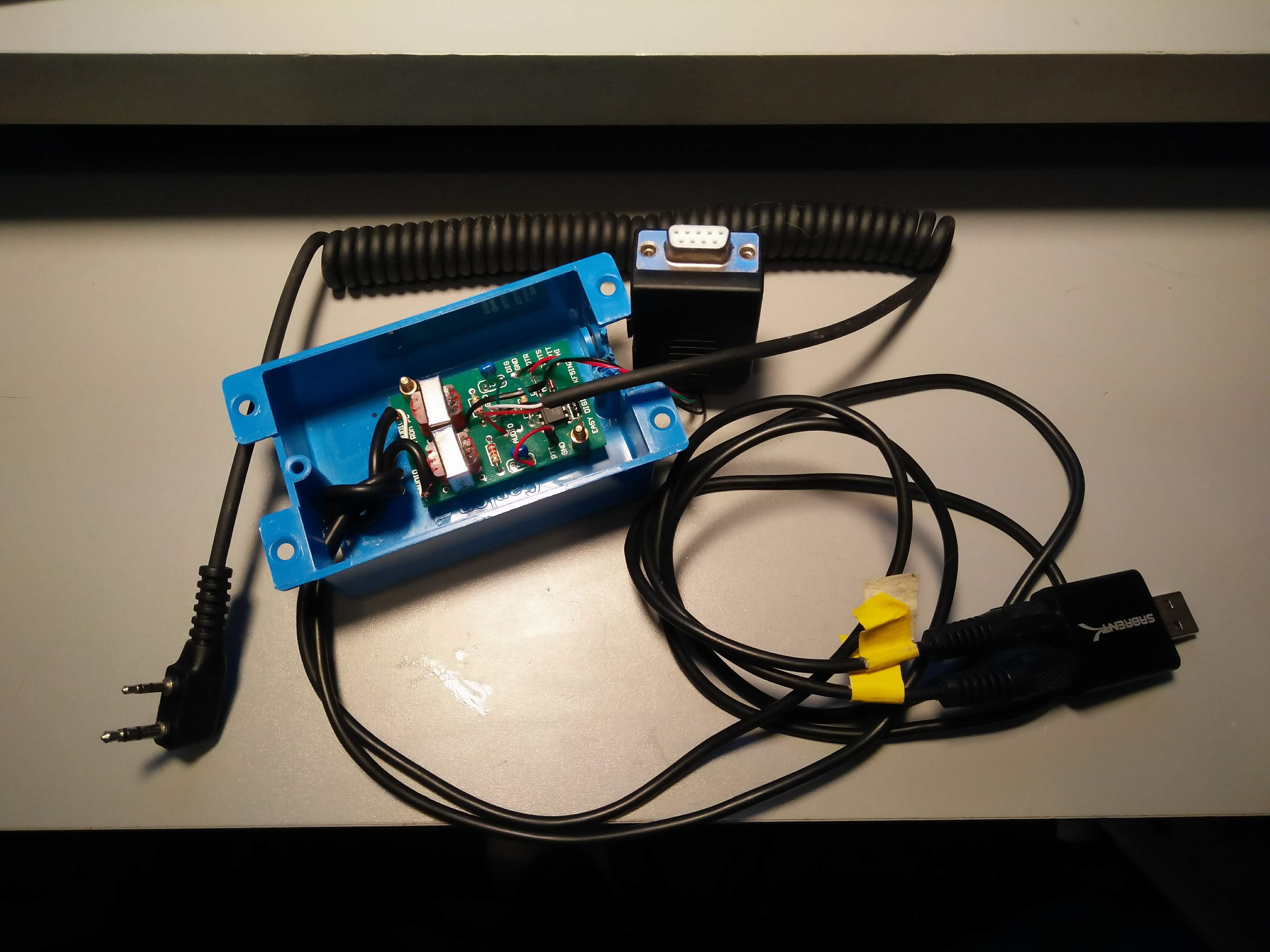
To give you context of the build, here is a picture of my interface mounted in a plastic electric box case. Note I use brass PC motherboard standoffs for the board that are screwed into the case.
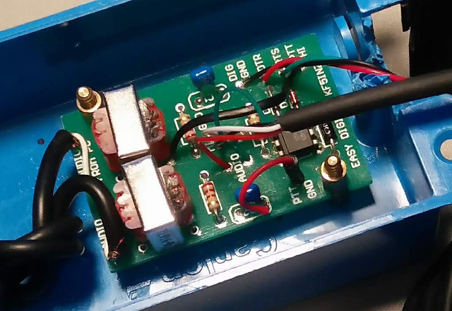
On the right side of the picture you see three wires twisted together that go to the DB9 Female breakout with the thick black cable being the Baofeng speaker/mic cable. Left side of the board are the audio cables going to the USB audio dongle. Below is a wider screenshot. I tied the audio cables into a not within the case to reduce any strain on the board.
Building from existing Digital Station setup from past posts
You can re-use the Baofeng audio interface cable and the USB sound dongle from my series on “Demonstrating Amateur Radio Digital Modes with Simple VHF/UHF Digital Stations” but you will have to transition all connectivity to and from the board to 3.5mm TRRS. Given those two components, the parts list would look like this;
- Easy Digi Kit ($8 USD)
- 3.5mm TRRS extension cable ($5 USD)
- 2 Male-to-Male Jumper wires ($5 USD for a bunch)PTT and Jumpers
- DB9 female terminal breakout ($3 USD)
- USB-to-Serial cable ($8 USD)
Know I have yet to build this and will update you when I do but the tasks required would look like in the following subsections.
Board and Cables
- Solder the Easy Digi included components to the board per the instructions provided by the kit.
- Cut the 3.5mm TRRS extension cable in half. We will be using the male half to connect from the board to the USB audio dongle and the female half for connection from the Baofeng audio cable to the board
- From the top of the board looking at the AUDIO FROM PC stencil with the 3.5mm TRRS male half, solder GND to the hole on the right side of the stencil and LEFT AUDIO to the hole on the left side of the stencil. We will not be using the RIGHT AUDIO connection since we only need one channel of stereo audio to the radio.
- From the top of the board looking at the AUDIO TO PC stencil, solder the MIC AUDIO to the hole on the right side of the stencil.
- Connect the Baofeng audio cable to the 3.5mm TRRS female cable and verify which wire from the 3.5mm TRRS female cable goes to what tips or rings on the Baofeng audio cable radio connector. Solder the 3.5mm TRRS female cable to the board as follows:
- SPK+ to RX AUDIO point closest to R3
- SPK- to RX AUDIO point closest to R1
- MIC+ to MIC IN
- MIC- to MIC GND
PTT Jumpers
- Triggering PTT on the Baofeng requires AUDIO, PTT, and MIC grounds to be connected together. We accomplish this by adding two jumpers to the component side of the board.
- For the first jumper, solder one end of a jumper wire into PTT GND. Snip the pin from the other end of that jumper wire and solder the wire to the side of C2 closest to PTT GND.
- For the second jumper, solder one end of a jumper wire into PTT HI and the other end to the open pin on the left bottom of T2 and above the left side of R2. That happens to be the same trace as MIC GND.
Serial and Connections
- Take three jumper wires cutting off the pins on one end of each, and strip a little insulation off the end.
- Solder the pin end of each jumper wire to DIG GND, DTR, and RTS holes on the board.
- Connect the other ends of the jumper wires to the screw terminals on the DB9 female breakout for GND (black), DTR (red), and RTS (blue) respectively as depicted in the picture below.
- Connect the USB-to-Serial cable to the PC and DB9 female connector.
- Connect the USB audio dongle to the PC and the 3.5mm TRRS male connector from the board to the USB audio dongle.
Interfaces: Build or Buy?
The Simple Interface I built is simple if you are a kit builder and not afraid of soldering. At $41 USD it may not be considered cheap. Switching out the DB9 serial and USB-to-serial cable to a USB-to-TTL solution only shaves $5 USD at best. Know the maker of Easy Digi sells a complete interface for Baofeng with PTT support via USB for around $47 USD not including shipping (search their store on eBay). If time is money buying may be a better option for you.
Reconfiguring Dire Wolf
With the hardware setup, we need to reconfigure Dire Wolf to send a PTT signal to the serial port via the USB-to-Serial connection. In Linux, the USB-to-Serial will usually register as /dec/ttyUSB) but in Windows it is less predictable showing up as COM4, COM5 etc. With the USB-to-serial attached you will need to go into Device Manager to find what COM port did it register as.
You can refer to my previous post on installing the Dire Wolf software and initial configuration. For PTT to be enabled you need to edit direwolf.conf and add the line below relevant to your operating system then restart Dire Wolf.
For Windows
PTT COM1 RTS DTR

For Linux
PTT /dev/ttyUSB0 DTR RTS
You can now disable using VOX on the Baoefeng if you were already doing APRS with YaaC on it from my previous post.
Update
I planned on doing a Part 2 to this post that included services such as a BBS. Sadly there are only two Packet BBS programs supported on Linux whose code base goes back to DOS days. I wanted to work with something a little modern and expandable. I went down the path of retrofitting MysticBBS which is still supported but with little success.
I still have some ideas on a simple Packet BBS to investigate but may not do so unless I hear from people interested in helping. Stay tuned.
For what it’s worth,
Joe, NE2Z