
Almost two years ago I did a post on a $15 CW transceiver you could build called the Pixie II CW QRP transceiver. As mentioned I bought the kit but only recently had a chance to finally put it together and get it on the air.
So if this is your first kit, here are some essential tools to help you get the most enjoyment out of kit building.
When it comes to desoldering I prefer using a vacuum solder sucker over using solder wick. For me it is easier to wield the solder pull in one hand while applying the iron to the part to be desoldered than use a wick.
Two other essential tools to make kit building enjoyable include helping hands vices and lighted head mounted magnifier lenses. Of course there are many tools out there people will suggest but I just wanted to cover the ones you will use all the time without breaking the bank if you have a limited budget.
As for building the kit.
Since the kit did not come with assembly instructions, I searched the web to see who else has built a Pixie and see what experiences they posted. For that I went with the article I suggested in my previous post. The Pixie I built is tuned for 40 meters on the QRP frequency of 7040 KHz.
I decided to go with building the kit inside an Altoids tin at first but it did not have enough real estate for how and where I wanted to mount my connectors and switch. So I went with a cigar tin that was not as deep but had more length and width. Here are a few pictures.
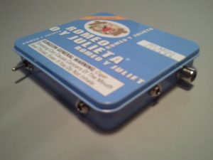
As you view the tin case from left to right you will see a SPST toggle switch for power, a stereo connector for audio, a stereo connector for a key, and a RCA female connector for the antenna.
Though the audio is mono, I went with a stereo connector since they are designed to accept mono and stereo male connectors. So know when you connect a stereo headphone to this you will only hear audio from one side. I went with a stereo connector for the key since male stereo is what I have on all my keys.
For the antenna connection I went retro rather than using the evolving standard of SMA connections for small RF devices. Personally, I am tired of spending alot of money on pigtails for SMA to SO-239. It is cheaper to go with a Motorola female for the antenna connector as found in older radios from 60s and then a single adapter to go from RCA female to SO-239.
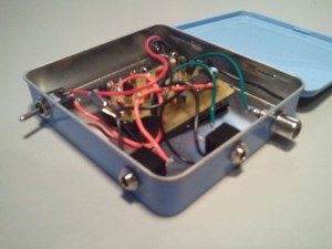
The PCB sits inside the tin case with plenty of electrical tape on the copper side to insure no shorting. The PCB floats freely so I just push it to one side to make space for the 9V battery.
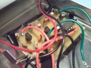
The picture above gives a closer view of where I attached buss wire for the connectors. I spent as much time planning connector layout, installing the connectors, and attaching them to the PCB as I did soldering up all the components on the PCB. Because the cigar tin is shallower than Altoids tin, I had to bend the crystal down a little.
So how does it perform?
I’ve done alot of DX and Field Day operations running only 5 watts with my Yaesu FT-817. Given the simplicity of the Pixie circuit and at best it transmits 300mW, I set my expectations low and would be satisfied with a working circuit and be able to hear a few signals. I plugged my G5RV to the Pixie using an SO-239 to RCA adapter, plugged in a battery, and then flicked toggle switch on.
What next?
Success with the Pixie inspires me to experiment further with QRP building. I bought a second Pixie with that purpose. Perhaps add CW side-tone so I can hear what I am sending, a variable cap to get some wiggle room on frequency.
For what its worth,
– Joe, NE2Z