
(Apologies for the long hiatus. The experiment in this post was done a year ago so I may have missed a few things in documenting it now.)
In my previous post I mentioned a repeater prototype for the HOPE XI conference I shelved in favor of going with commercial gear that became available. After the conference I continued taking the prototype towards something a little bit better.
Hardware revisited
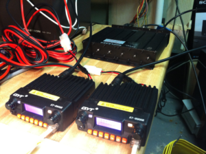
For the RF portion of the repeater I continued with the pair of QYT-KT8900R radios as transmitter and receiver, a UHF duplexer, and a VHF/UHF base antenna. For the repeater controller I stayed with the Raspberry Pi 2 running SVXlink server software.
The audio interface remained a USB sound dongle with the received audio from the external speaker jack on the receiver to the mic port on the USB sound dongle. The transmitted audio (speaker out on the USB sound dongle) was connected directly to an Easy DIGI interface for isolation and control and then onwards to the mic audio pin on the mic jack of the transmit radio.
The control interface was SVXlink configured for VOX on receive and serial control for transmit. The serial connection was a USB-to-Serial device to an Easy DIGI interface which in turn connected to the PTT pin on the mic jack of the transmit radio.
Interface changes
The heart of SVXLink is it being “a general purpose voice services system.” As such it has awesome audio capabilities in the detection of DTMF, CTCSS, besides providing VOX. But enabling all that capability on a Raspberry Pi is resource intensive and prone to false positives/negatives. So I decided to limit SVXlink’s audio detection duties to DTMF only and defer CTCSS detection to setting the receiver for CTCSS squelch.
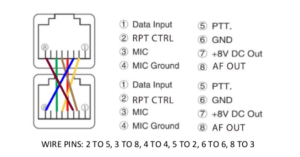
VOX for signal detection can be tricky and is why a carrier detect/COS/COS is best practice when it comes to repeaters. So I was interested to find out that the QYT KT8900R had an undocumented feature that presents carrier detect on the microphone jack. I discovered this when I found out about it’s BTECH cousin published a document on building a cross-band repeater with two of the radios just using a custom wired cable CAT5 wire connected between the microphone jacks on each. Exploiting this capability could allow me to switch from VOX to carrier detect controlled by GPIO pins on the Raspberry Pi.

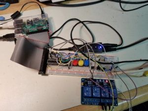
Switching to GPIO meant to key the transmitter I no longer needed the overhead of USB control, USB-to-Serial conversion, and the Easy DIGI interface. Instead I could have the GPIO pin drive a relay to set the required state of the PTT pin on the transmitter to key it.
Software changes
SVXlink is well documented and requires taking the time to go through the man pages. Changing from VOX to GPIO keying of the transmitter occurs in the svxlink.conf file. Changes in the file include PTT_TYPE=GPIO and PTT_PIN=gpio18 which sends a logic HIGH on gpio pin 18 (this pin number is only used as an example.) If you need the output to be a logic LOW then the setting would be PTT_PIN=!gpio18. The joy in switching away from VOX is no longer having to spend a ton of time on tweaking all the audio and timing settings in svxlink.conf
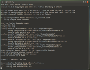
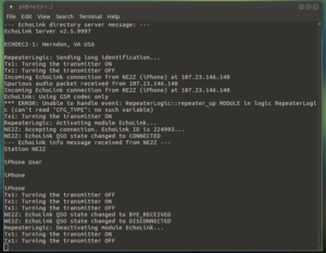
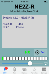
Results from the bench
It works! Details are better described with the pictures that follow and the captions underneath them.
Bells and Whistles
In days of old, it was pretty exciting for repeaters to have features such as a phone patch (aka autopatch) or various informative messages played depending on the DTMF tone combinations you entered. While EchoLink connectivity supplants the excitement of autopatch, I decided to see if I could bring some of DTMF excitement back with my bench repeater.
After spending time understanding the software structure of SVXlink and gaining a minimum understanding of how to program in Tcl language I was able to create a crude “Magic 8 Ball” response when a sequence of DTMF tones was entered. The responses were WAV files I created that would be randomly played. Since it has been a while since I worked the feature perhaps I will get a chance to “re-learn” my work and post it here if enough people are interested.
Epilogue
Experimenting with the “Magic 8 Ball” feature is where I left off on this project and then shelved it until I got the inspiration to design and make a proper circuit board for the interface and more importantly and/or and opportunity to get it out of the lab and good enough to run a proper repeater site reliably. Til then it is off to other projects.
For what its worth,
– Joe